Hand-eye calibration
This tutorial guides you through the hand-eye calibration process with Roboception’s URCap. During this procedure, the spatial relationship between the camera and the robot system is established.
The camera can be used in two ways: either statically mounted in the workspace or attached directly to the robot. This choice determines how the calibration is performed and the type of transformation established. For detailed information on the calibration principles, refer to the Hand-eye calibration documentation.
Before you begin, ensure that you have completed the tutorials Getting started and Tuning of image parameters.
Static camera
In this configuration, the camera is mounted statically in the workspace, and the calibration grid is attached to the robot. The hand-eye calibration determines the transformation between the camera and the robot base frame. Ensure the camera is mounted rigidly, completely stable, and unaffected by robot movements or vibrations.
Mounting the calibration grid
The calibration grid can be securely mounted to the robot using a mounting adapter. You can use the available manufacturing files to create this adapter yourself.
Manufacturing the adapter
The manufacturing files for the grid adapter can be downloaded from the Customer area download page.
We strongly recommend milling the adapter out of aluminum. The adapter must not be 3D printed. Rigidity of the adapter must be guaranteed for the hand-eye calibration to be accurate. The slightest flex in the adapter will significantly degrade calibration accuracy.
Note
Roboception is not responsible for any breakage, equipment damage, or inaccuracies resulting from the use of a self-manufactured adapter.
Warning
If the manufactured adapter exhibits any flex or play, the resulting calibration will be inaccurate. Always ensure a rigid mounting.
Required tools and materials
- T30 Torx driver
- Torque wrench (capable of 4 Nm and 8 Nm)
- Calibration grid mounting adapter
- 8 M6x16mm lens head T30 Torx screws
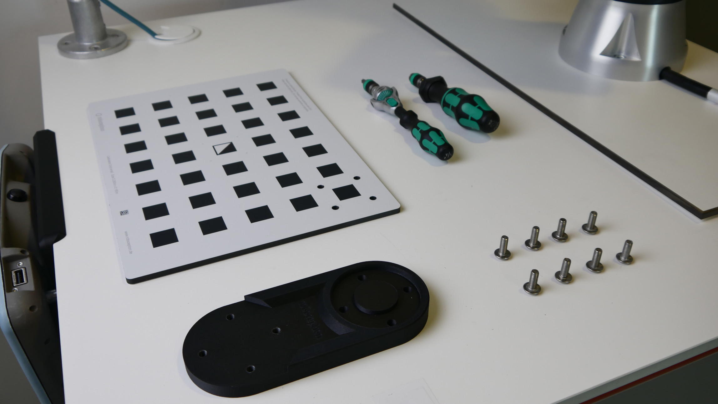
Fig. 60 Required tools and materials for grid mounting
Mounting procedure
- Attach grid to adapter:
- Locate the four mounting holes in the upper-right corner of the calibration grid
- Mount the calibration grid to the adapter using four M6x16mm screws
- Tighten each screw to 4 Nm using the torque wrench
- If no torque wrench is available, hand-tighten the screws carefully. Avoid over-tightening!
- Mount adapter to robot:
- Set wrist joint 3 of the robot to its neutral position (0°), with the flange alignment hole pointing away from the robot base
- Select appropriate adapter orientation based on your workspace constraints
- Secure the adapter to the robot flange using the remaining four M6x16mm flange screws
- Tighten each screw to 8 Nm using the torque wrench
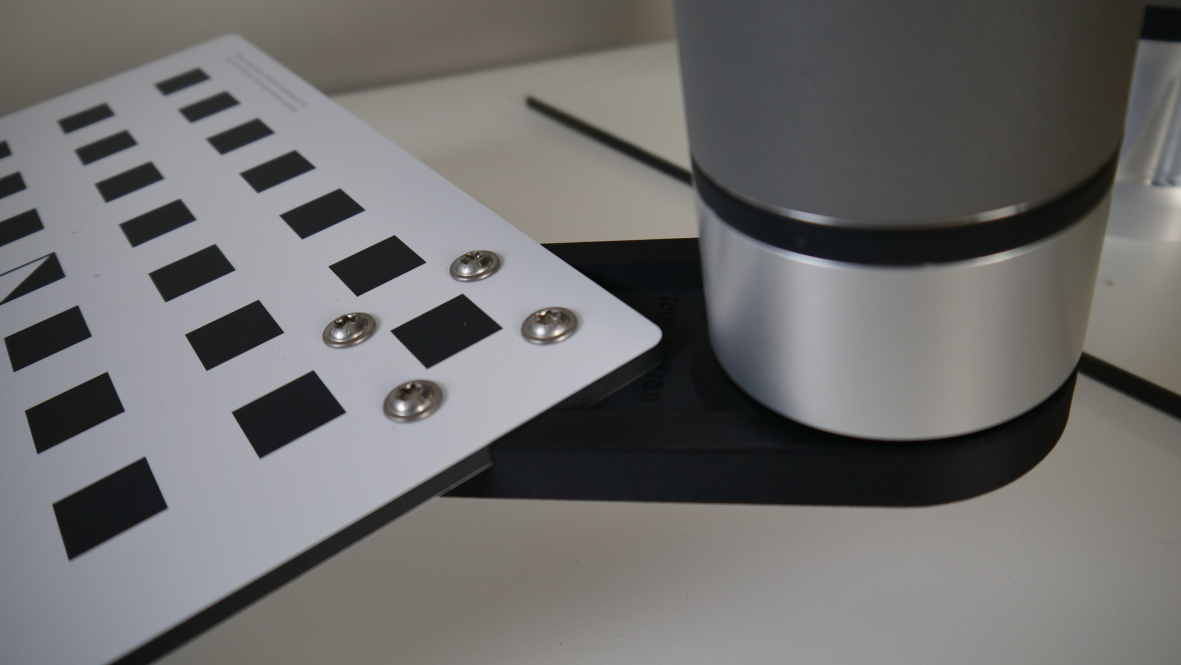
Fig. 61 Calibration grid properly mounted using the adapter
Warning
Over-tightening the screws can bend the grid and impair calibration accuracy. Always use the specified torque values.
Note
The neutral flange position ensures maximum range of motion during calibration. While the adapter can be mounted in different orientations, consider your workspace constraints when choosing the mounting position.
End effector configuration
Before starting the calibration, the correct payload and Tool Center Point (TCP) must be configured. A correct payload configuration ensures precise robot positioning and makes the free drive mode more responsive for teaching poses during calibration.
- Navigate to Installation → General → TCP in the UR menu. Create a new TCP with the name ‘Calibration Grid’. An arbitrary TCP-transformation could be used, but a zero-transformation is recommended such that the TCP coincides with the tool flange.
- Navigate to Installation → General → Payload in the UR menu. Use the UR’s built-in payload measurement function to determine the calibration grid payload and apply the measured settings.
- Click ‘Save…’ in the top bar → ‘Save Installation as…’ and name it ‘Calibration Grid’.
Note
For more information on TCP and payload configuration, please refer to the official Universal Robots YouTube tutorial on Tool Configuration: TCP, orientation, payload & center of gravity.
Robot-mounted camera
In this configuration, the camera is mounted on the robot, while the calibration grid is fixed in the workspace. The hand-eye calibration determines the transformation between the camera and the TCP selected during the calibration.
Warning
The transformation between the TCP and the camera will be used to compute object poses relative to the robot’s base frame when triggering detections, using the robot’s current pose. Therefore, it is crucial to use the same TCP during calibration and subsequent detection applications.
The camera must be mounted securely to the robot flange using appropriate mounting hardware. The mounting must be rigid and stable, free from any movement or play, and capable of withstanding robot accelerations without shifting.
Mounting the calibration grid
Securely fixate the calibration grid in the workspace, ensuring it remains immobile during calibration. Position the grid so it is clearly visible to the camera and allows ample space for robot movement.
End effector configuration
- Mount the end effector required for your application.
- Navigate to Installation → General → TCP in the UR menu. Verify that the correct end-effector TCP is selected.
- Navigate to Installation → General → Payload and use the built-in payload measurement function to measure the complete payload (including end effector and mounted camera).
- Click ‘Save…’ → ‘Save Installation as…’ → name it ‘Gripper with Camera’.
Note
For more information on TCP and payload configuration, please refer to the official Universal Robots YouTube tutorial on Tool Configuration: TCP, orientation, payload & center of gravity.
Using the hand-eye calibration program
The program is identical for both mounting configurations. It guides the robot through a series of poses that have to be taught before. During calibration, the robot moves with linear tool-space motion, a tool speed of 0.5 m/s, and a tool acceleration of 0.5 m/s².
Step-by-step calibration
- Create an empty program
- Add the ‘rc hand-eye calibration’ program node
- In the node, select your sensor and configure the mounting type and grid size
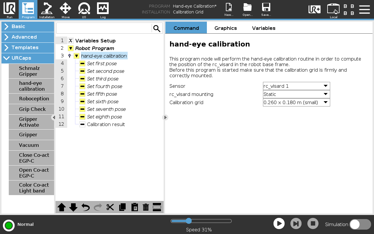
Fig. 62 Setting parameters in the rc hand-eye calibration node
- For each of the eight ‘Set pose’ nodes:
- Refer to the reference image in the program node for guidance
- Move the robot to achieve a similar grid position in the live camera view
- Click ‘Store waypoint’ button once positioned
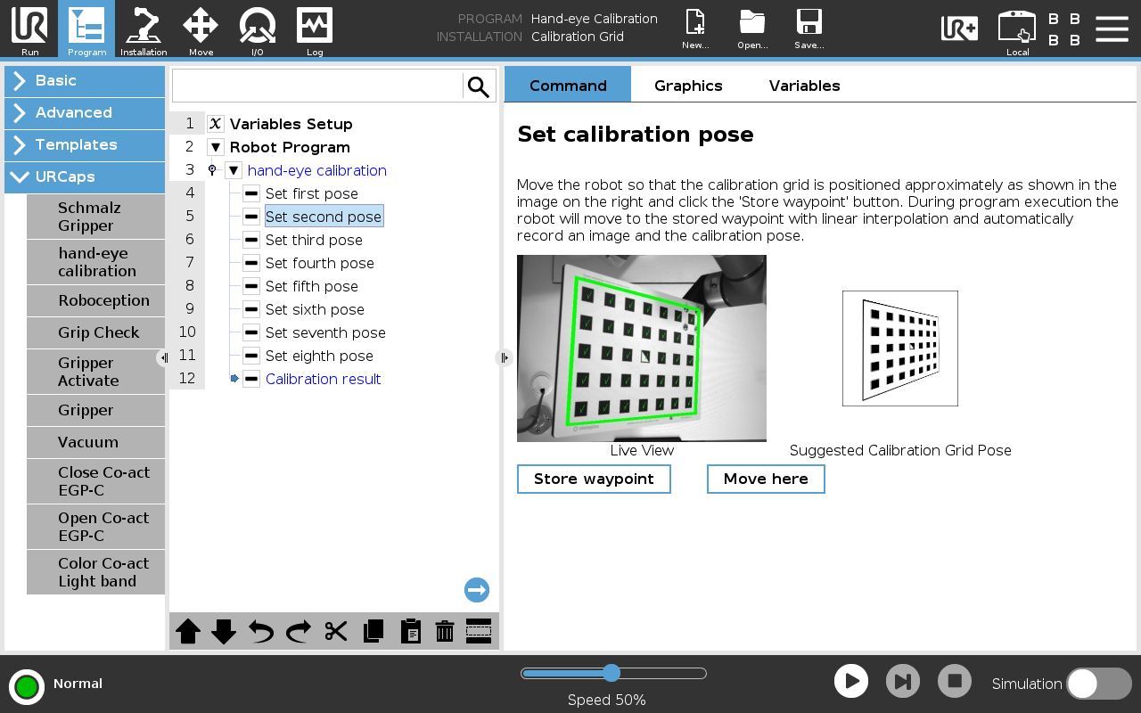
Fig. 63 Set pose node
- Execute the program at around 25% speed initially to react to potential collisions.
- After successful calibration:
- Review the results in the ‘Calibration result’ node
- Store the calibration if error values are acceptable (typically less than 2mm)
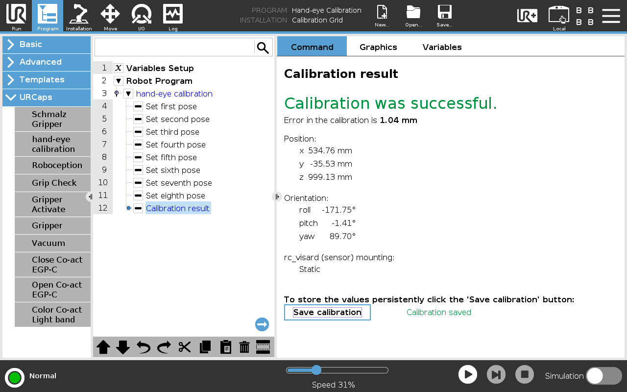
Fig. 64 Calibration result node
Note
While positioning the robot, use the free drive mode while remaining in the calibration pose node to adjust the position. This keeps the live view visible during adjustment. Consider using the constraint-free drive mode for easier positioning in certain cases.
Note
The reference images provided only serve as guidance. What is crucial is capturing eight distinctly different poses of the calibration grid.