End-to-end system accuracy test
Introduction
Hand-eye calibrations can degrade over time due to small physical changes in your system setup, such as slight camera movements. This degradation typically manifests as inconsistent gripping behavior - objects may be gripped with an offset that varies depending on their workspace position. While this offset can be temporarily compensated for in a specific orientation, the problem will reappear when the objects are moved to different locations or orientations.
This tutorial guides you through a systematic verification process to assess your complete system’s accuracy and identify potential issues. The test uses AprilTag markers and a precision pointing tool to verify the accuracy of the entire chain from vision detection to physical robot positioning.
Requirements and setup
Verification sheet
Download the End-to-end System Accuracy Check sheet. It displays two AprilTags positioned in opposite corners with a center crosshair marker between them.
Print the sheet in high quality, black and white. Mount the print on a planar but soft surface, such as foam board or cardboard. This allows the pointing tip to safely penetrate the paper if positioning offsets occur during verification.

Fig. 65 Verification sheet showing AprilTags and center marker
Pointing tool requirements
For optimal accuracy, we strongly recommend using a rigid, dedicated pointing tool with a sharp tip (such as a dart tip) mounted directly to the robot flange. While it is possible to use a pointing tip attached to a flat surface for pickup with a suction gripper, this approach should only be used if the tip’s stability can be guaranteed, for example through a multi-cup suction gripper setup. The key requirement is that the tool provides a precise, sharp point that remains completely stable during measurements.
TCP configuration
Configure the tool settings in your robot system:
- Navigate to Installation → General → TCP in the UR menu
- Create a new TCP named ‘Pointing Tool’
- Configure the TCP transformation to match the physical tip position
- Navigate to Installation → General → Payload
- Use the built-in payload measurement function
- Save the configuration as ‘Pointing Tool’
Note
For more information on TCP and payload configuration, please refer to the official Universal Robots YouTube tutorial on Tool Configuration: TCP, orientation, payload & center of gravity.
Before proceeding, verify your TCP configuration:
- Position the tool tip near a fixed reference point
- Rotate the tool around its Z-axis by navigating to the Move Menu, selecting Feature Tool and then changing the TCP Orientation
- The physical tip should remain perfectly stationary during rotation. If the tip moves in a circular pattern, reconfigure the TCP
Warning
TCP accuracy is crucial for reliable measurements. Even small offsets can significantly impact your verification results.
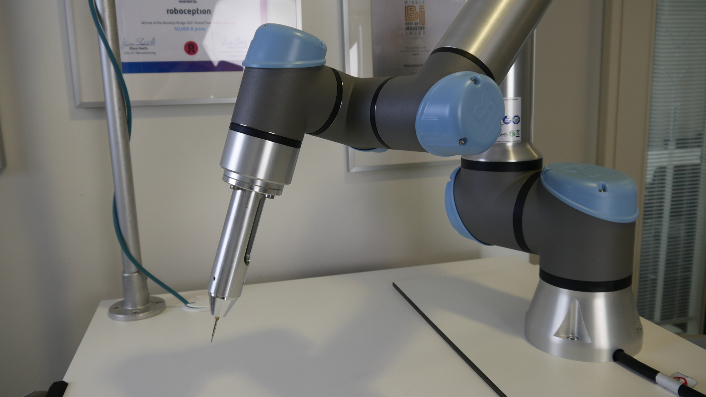
Fig. 67 Pointing tool mounted to the robot flange
Verification process
The verification process combines vision and robotics to test the hand-eye calibration accuracy. First, the vision system detects both AprilTags on the verification sheet to establish their precise positions. Using these positions, the robot calculates the exact center point between the tags. The robot then moves the pointing tool’s tip to this calculated position. If the hand-eye calibration is accurate, the physical tip of the tool will align perfectly with the printed center crosshair marker on the sheet.
Program setup
- Download the verification program zip file:
End-to-end System Accuracy Test - Unzip the file, providing you a .script, a .urp and a .txt file
- Import the files into your robot using a USB stick or an SSH connection
- Open the ‘Pointing Tool’ installation you created in the step before
- Open the ‘End-to-end System Accuracy Test’ program
- Select the ‘out_of_way’ waypoint in line 4, and use ‘Edit Pose’ to teach a pose with the robot not obstructing the camera view
Program execution
With the setup complete, lower the program speed to 30% and execute the program. The program is designed to run multiple passes - complete 5-6 passes, placing the verification sheet in a new position and orientation for each iteration.
In each pass:
- The robot moves to the ‘out_of_way’ waypoint, then shows a popup asking to trigger a detection
- Place the verification sheet in your workspace, ensuring the center is reachable by the robot
- ‘Continue’ will trigger a detection, then show the calculated center point in another popup
- ‘Continue’ will move the robot to 10cm above the center point, and then slowly lower the tip towards the center point
- The program shows a popup indicating the center has been reached
- Measure the deviation of the tool tip on the target with a ruler or a caliper gauge
- ‘Continue’ will move the robot 10cm upwards
Test different configurations by:
- Varying positions across the workspace
- Changing sheet orientations
- Using multiple heights (if applicable)

Fig. 68 Out-of-way position popup
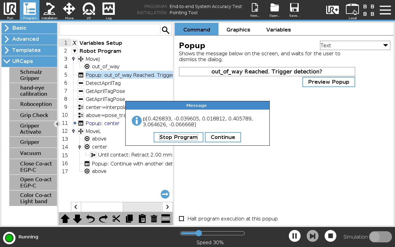
Fig. 69 Center point popup
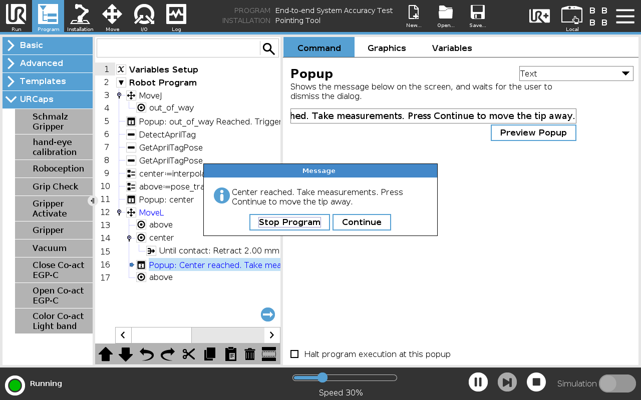
Fig. 70 Center reached popup
Interpreting results and next steps
A successful verification shows the pin consistently touching the center marker, regardless of sheet position or orientation. Small offsets of less than 2 mm may be acceptable depending on your application requirements.
Watch for these indicators of potential problems:
- Consistent offset from the center marker
- Position-dependent accuracy variations
- Different results based on sheet orientation
For unsatisfactory results, first perform a complete recalibration using the Hand-eye calibration procedure. If accuracy issues persist after recalibration, please contact Roboception support for further assistance.