Tuning of image parameters
Parameters like the frame rate, exposure time and gain factor determine when and how images are captured. They have a huge impact on all image processing modules on the rc_visard. Additionally, the quality of the depth image can often be improved by tuning stereo matching parameters.
This tutorial describes the steps for tuning parameters to get the best quality for stereo and depth images.
Before we start
This tutorial applies to all rc_visard models. However, it does not focus on parameters related to color sensors as most modules are based on monochrome images.
- The rc_visard must be running and connected to a network or directly to a computer.
- The Web GUI of the rc_visard should be opened in a web browser. This can be done with the discovery tool from Roboception.
- The rc_visard has the latest firmware (version 26.04). The firmware version can be verified on the page of the Web GUI.
This tutorial focuses on the Web GUI to set the parameters. It is also possible to use GigE Vision 2.0/GenICam image interface and the REST-API interface for setting the parameters.
Note
All parameter changes are immediately applied and persistent across reboots.
Camera Parameters
The Camera page of the Web GUI shows the left and right images and permits changing and saving the parameters.
Frames per Second (FPS)
An important issue is the frequency with which the rc_visard delivers images. Internally, the rc_visard always captures images with 25 Hz as some on-board modules, like visual odometry, require a constant frame rate. The FPS setting determines how many of the internally captured images are sent out via the GigE Vision interface. Reducing the FPS significantly reduces the network load as well as some computational burden of the rc_visard and the receiving host computer. Therefore, in many applications, the FPS can and should be reduced.
However, some on-board modules like stereo matching and others only work on images that are also sent via GigE Vision to ensure that the output of the modules can always be accompanied by their input images. This means that the FPS setting also has an effect on the maximum frame rate of other modules. Furthermore, a lower FPS setting can increase the latency, i.e. the time it takes until a module can start working and delivering a result.
Note
The optimal FPS setting very much depends on the application. In the case that images are streamed via GigE Vision, it is recommended to reduce the FPS setting if possible, but keeping the drawback of higher latency in mind.
Exposure and Gain Settings
The exposure time is the time during which the light of the scene is collected. It influences how bright the captured image appears. The exposure time is typically in the order of several milliseconds. If there is less light in the scene, then a longer exposure time is required. However, long exposure times cause blurring, if objects in the scene or the rc_visard itself moves.
The second parameter that influences the image brightness is the gain factor. It amplifies the signal in the chip and makes the image appear brighter, but it also increases image noise. The gain can only be set in steps of 6 dB. Each step doubles the brightness.
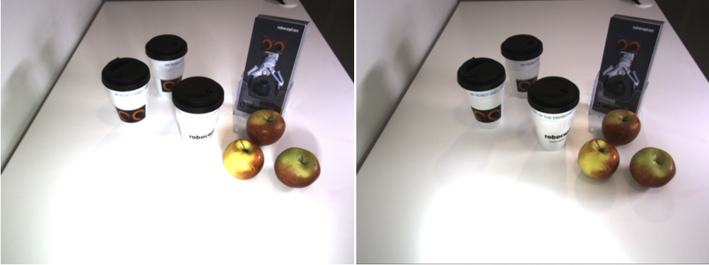
Fig. 3 The picture on the left is overexposed on the table in front as well as in the relevant scene part that contains objects. This should be avoided. The image on the right is overexposed on the table, but the relevant scene part is properly exposed.
Automatic Mode
The automatic mode is the default for the rc_visard and is recommended for most cases. It tries to maintain an average image brightness by using the exposure time up to a limit that can be changed depending on the movement of the scene or the sensor. If the scene or the sensor move fast, the maximum exposure time should be low to avoid image blur during movements. The automatic mode always keeps the exposure time below the maximum setting and uses the gain factor to increase the image brightness if necessary. As mentioned above, this introduces noise.
Therefore, the maximum exposure time should be increased if image capture during scene or sensor movements is not required or if these movements are rather slow. In such cases, the exposure time should be large enough to achieve a very small gain factor, ideally 0.0 dB.
In automatic mode, it may take a few seconds until the exposure and gain settings become stable, especially if the scene contains very dark and very bright regions.
Note
The automatic mode is recommended in most situations, especially if the scene content or the lighting can change.
If images relevant for the application are taken during movement of the rc_visard or the scene, then the maximum exposure time should be limited, depending on the speed of movement. 5 ms to 7 ms is a good starting point. In case of high gain values, it should be considered to increase lighting.
If relevant images are only taken while the scene and rc_visard are static, then the maximum exposure time should be increased to the maximum, especially in situations without sufficient light.
Using an Exposure Region
In many applications, only a part of the image is relevant. If the relevant image part is known and does not change, then an exposure region can be defined around it. In this case, the automatic mode optimizes the exposure and gain settings only for the content of the exposure region and neglects all other images parts. This can be a very powerful tool as very dark or very bright areas outside the exposure region cannot negatively influence the relevant image part inside the exposure region.
The exposure region can be specified from the Web GUI and via the REST-API interface. If an exposure region is specified, it is visualized as a rectangle in the left camera image in the Web GUI.
There are four parameters that define the exposure region: exp_offset_x, exp_offset_y,
exp_height and exp_width.
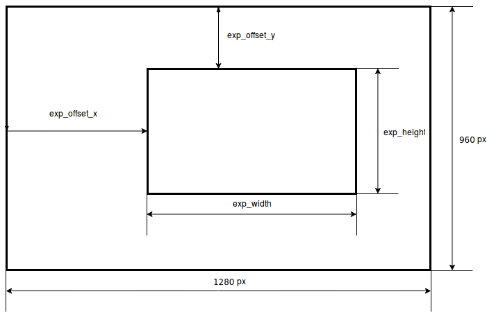
Fig. 4 The outer rectangle represents the whole image and the inner rectangle represents the chosen exposure region.
For setting the exposure region via REST-API, a PUT request must be sent to the URL
http://<rc_visard_ip>/api/v2/pipelines/0/nodes/rc_camera/parameters, where <rc-visard-ip>
should be replaced by the actual IP of the rc_visard. For setting the exposure region to
a size of 800x600 pixels that starts in image column 150 and image row 80, the following
data must be sent:
[
  { "name": "exp_offset_x", "value": 150 },
  { "name": "exp_offset_y", "value":  80 },
  { "name": "exp_width",    "value": 800 },
  { "name": "exp_height",   "value": 600 }
]
This can be done via the built-in Swagger UI, or from a shell via curl:
The Swagger UI can be reached at
http://<rc-visard-ip>/api, where<rc-visard-ip>is the actual IP of the rc_visard.Under pipeline nodes, select
PUT /pipelines/{pipeline}/nodes/{node}/parametersTry out the call with the following values:
- node:
rc_camera - parameters:
[
  { "name": "exp_offset_x", "value": 150 },
  { "name": "exp_offset_y", "value":  80 },
  { "name": "exp_width",    "value": 800 },
  { "name": "exp_height",   "value": 600 }
]
- node:
The following command assumes that the variable RC_VISARD_IP is set to the actual IP of the
rc_visard (e.g. RC_VISARD_IP=10.0.2.90).
curl -X PUT "http://$RC_VISARD_IP/api/v2/pipelines/0/nodes/rc_camera/parameters" -H  "accept: application/json" -H  "Content-Type: application/json" -d \
"[ \
   { \"name\": \"exp_offset_x\", \"value\": 150 }, \
   { \"name\": \"exp_offset_y\", \"value\":  80 }, \
   { \"name\": \"exp_width\",    \"value\": 800 }, \
   { \"name\": \"exp_height\",   \"value\": 600 } \
]"
The following command assumes that the variable RC_VISARD_IP is set to the actual IP of the
rc_visard (e.g. set RC_VISARD_IP=10.0.2.90) and the curl command is in the path.
curl -X PUT "http://%RC_VISARD_IP%/api/v2/pipelines/0/nodes/rc_camera/parameters" -H  "accept: application/json" -H  "Content-Type: application/json" -d ^
"[ ^
   { \"name\": \"exp_offset_x\", \"value\": 150 }, ^
   { \"name\": \"exp_offset_y\", \"value\":  80 }, ^
   { \"name\": \"exp_width\",    \"value\": 800 }, ^
   { \"name\": \"exp_height\",   \"value\": 600 } ^
]"
The following command assumes that the variable RC_VISARD_IP is set to the actual IP of the
rc_visard (e.g. $RC_VISARD_IP="10.0.2.90").
Invoke-RestMethod "http://$RC_VISARD_IP/api/v2/pipelines/0/nodes/rc_camera/parameters" -ContentType 'application/json' -Method Put -Body '
[
   { "name": "exp_offset_x", "value": 150 },
   { "name": "exp_offset_y", "value":  80 },
   { "name": "exp_width",    "value": 800 },
   { "name": "exp_height",   "value": 600 }
]' | ConvertTo-Json -Depth 6
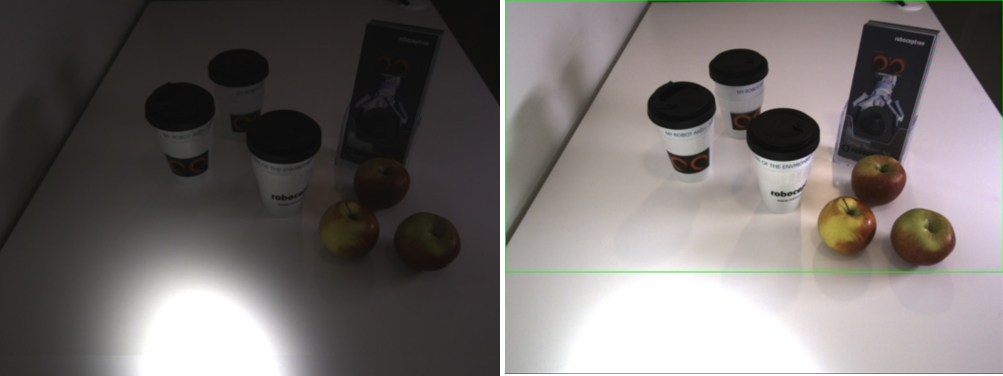
Fig. 5 Both pictures were taken in auto exposure mode with the same exposure parameters. The second picture was taken after defining an exposure region (represented by the green frame).
Note
It is recommended to use an exposure region only if a part of the image is relevant for the application and if this part does not change.
Manual Exposure and Gain
In cases where the lighting is constant and the scene always has a similar overall brightness, then exposure and gain can be set manually.
Setting the exposure time and the gain factor manually permits to focus on scene parts that are relevant to the application, e.g. some objects in the middle of the scene. Thus, overexposure within the area of interest must be avoided, but can be tolerated in scene parts that are not relevant for the application.
As a general rule, overexposure is worse than underexposure for image processing, because the information in overexposed regions is lost due to saturation of pixel values. In contrast, underexposed regions often contain enough information for image processing modules. Therefore, it is better to set parameters such that images are darker.
Fig. 6 The picture on the left is overexposed on the table in front as well as in the relevant scene part that contains objects. This should be avoided. The image on the right is overexposed on the table, but the relevant scene part is properly exposed.
The gain factor should only be increased in low lighting conditions or to reduce the exposure time for avoiding motion blur. As a general rule, the gain factor should always be set as low as possible.
Note
It is recommended to set exposure and gain manually only if the lighting and scene content do not change. The gain factor should be chosen as low as possible. Overexposure in relevant scene parts or on relevant objects must be avoided. Underexposure can be acceptable.
Depth Image Tuning
The Depth Image page of the Web GUI shows the left, disparity and confidence image and permits changing and saving depth image related parameters.
Working Range
First, the working range of the application should be considered. Setting the Maximum Distance parameter to a certain value invalidates all pixels in the depth image that are further away. This is an easy way for excluding scene parts that are not relevant for an application.
Similarly, the Minimum Distance parameter can be increased if it is certain that no object will ever be closer to the rc_visard than the given distance. Increasing the minimum distance has the benefit that it also reduces the runtime for computing the depth image and therefore increases the frame rate.
Frequency
In some applications, the frequency or latency with which depth images are computed is more relevant than the quality of depth values. In this case, the default Quality High can be reduced to Medium or Low. Depth images of a lower quality are computed by reducing the image resolution before stereo matching. This reduces the runtime and increases the possible framerate significantly. However, the framerate for computing depth images is always limited by the camera framerate setting.
As discussed above, the minimum distance should be increased if possible for the application as this also helps to reduce runtime and increase the frequency.
Increasing Density
Depth images often contain invalid values that appear black in the depth image that is shown in the Web GUI. This happens for scene parts that are outside the defined working range, as discussed above, as well as on the left side of objects, because here, a part of the background is not visible in the right camera image. This is called an occlusion and it is absolutely normal.
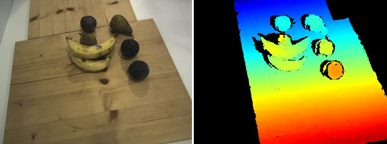
Fig. 7 Left camera image and colored, dense disparity image. Blue means far away and red means close. All black areas are invalid, i.e. depth cannot be determined. Invalid areas on the left side of objects are due to occlusions, which is normal. Untextured areas are typically invalid as well.
Other cases of invalid pixels are typically unwanted. In general, invalid pixels are due to the inability of the stereo matching method to compute depth. There are various reasons for it. Five different (and complementary) strategies to increase the density of depth images are discussed in the following:
Adjusting image exposure
Overexposed areas do not contain enough information for matching and therefore appear invalid. Furthermore, areas may appear invalid if the image noise is stronger than the texture. Both problems can be solved by setting the exposure and gain settings correctly as explained in Section Exposure and Gain Settings.
A sparse depth image can also be caused by changing lighting conditions, when the SingleFrame or SingleFrameOut1 acquisition modes are used. For example, if a bright robot arm moves through an otherwise dark scene just before image acquisition, the camera images might be underexposed and lead to a sparse dense depth image. Users can therefore allow the camera to wait a brief period before taking an image, so that the rc_visard has more time to adjust the exposure time. This feature permits the camera to ignore transitory effects disturbing the auto exposure control before settling on an optimal exposure time. One can enable this feature by increasing the Exposure Adaptation Timeout in the Depth Image Settings.
Exploiting static scenes
If the scene and the rc_visard do not move during image capturing, then the Static mode is recommended. In this mode, the rc_visard internally accumulates eight consecutive images at the frame rate of 25 Hz (regardless of the user’s framerate setting), and averages these images to reduce noise. This permits stereo matching even for weakly textured objects, and makes the depth image often much more dense.
Changing the sensor orientation to accommodate horizontal lines
One common case for missing objects in depth images is due to the horizontal orientation of straight objects. This alignment along image rows (that also means parallel to the baseline of the stereo system) can make stereo matching impossible. It can be easily determined if this the case by slightly rotating the rc_visard or the object and observing if the orientation has an effect on the appearance of the object in the depth image. If this is the case, then an orientation should be chosen to avoid it.
Improving the scene’s texture through a projector
One of the most common reasons for invalid areas in indoor environments is the lack of texture as well as strongly repetitive texture. Typically, walls and tables are unicolor without any texture. Other structures are highly repetitive. Both cases do not permit a proper stereo matching process. These objects and scene parts may not be important for the application, but if they are, then the only way to capture them is by adding an artificial texture by projection. Random dot projectors, such as the rc_randomdot projector, are best suited in this case. The Obtain dense depth images with the rc_randomdot projector tutorial describes the setup of the rc_randomdot projector.
Filtering errors
Finally, there are many ways to filter possible errors as explained in the Error Filtering Section. Filtering errors means to set the critical depth values to invalid. The Fill-in parameter can be used to interpolate small areas that are typically caused by error filtering. Higher fill-in values increase the number of areas that can be interpolated. The size of areas that are interpolated directly depends on the segmentation setting for error filtering.
Filtering Errors
Errors fall into two categories. Outliers, which are typically small patches of depth values that can appear anywhere in the working range and geometric errors that are close to the real depth.
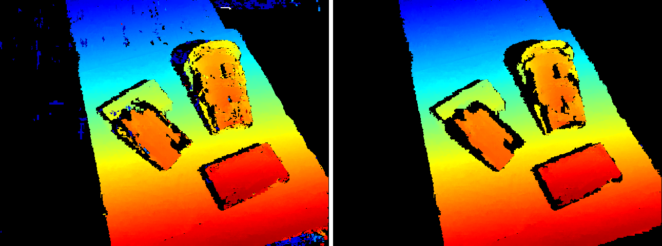
Fig. 8 Disparity image with small outlier regions in the left, visible as spots in different colors. The image on the right shows the result after applying the segmentation filter and fill-in, for removing outliers and filling small invalid areas.
Outliers can be filtered out using the Segmentation parameter. The parameter gives the maximum number of connected pixels that are filtered out. All patches with less than this amount of pixels are set to invalid. The size is also used for the fill-in parameter that is explained in the Increasing Density Section, so that holes that are caused by this filter are typically interpolated.
Another way to reduce the likelihood of outliers is to increase the Minimum Confidence as the confidence is the probability that a pixel is not an outlier.
Depth values that have a potentially high geometric error can be filtered using the Maximum Depth Error parameter.
Reducing Noise
For some applications, it is necessary that the surfaces in the depth image are smooth. This can be achieved by enabling the Smoothing option.
Finally, increasing texture also reduces noise in the depth image. As mentioned in the Increasing Density Section, a separate random dot projector can be used to add texture to the scene.