Network configuration
The rc_visard offers several options to connect and configure it to your network setup as shown below. In this tutorial we show how to properly configure the rc_visard’s IP settings as well as optimizing the host PC’s network settings for the high data throughput.
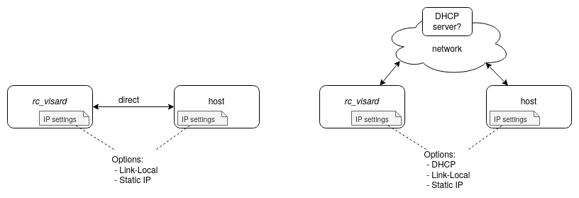
Fig. 10 The rc_visard can be connected either directly to the host PC (left) or via a larger network (right). In terms of IP settings it supports configuration via DHCP, via Link-Local, or with a static IP address.
Note
Generally, we recommend to connect the rc_visard directly to the host PC whenever possible because configuration, troubleshooting, and network optimization involves maximally two devices and not a larger network with possibly many switches, a DHCP server, and the like.
Before we start
Before going through this tutorial, the following prerequisites should be met.
Have the rc_visard’s serial number at hand
It is an 8-digit number to be found on the device and will
be referred to as rc_visard_id in the remainder of this tutorial.
Clarify network setup
- Check the host’s network settings, i.e. IP address and sub-net mask. If you want to connect the rc_visard to the host via Link-Local please make sure the host is configured accordingly.
- Is the rc_visard directly connected to the host or via a larger network?
- If connected to a larger network, contact your system administrator and check:
- Is a DHCP server available in the network? In some networks, the DHCP server is configured so that it only accepts known devices. In this case, the sensor’s MAC address (to be found on the device’s label) needs to be configured in the DHCP server.
- What kind of network switches are installed in that network? The switches should support jumbo frames and have a high enough switching bandwidth to not drop packets.
Download and install client software on host PC
- Download and install Roboception’s discovery tool rcdiscover-gui.
- Optional: Download and install Roboception’s command line GenICam tools.
Connect and discover the rc_visard
Once the rc_visard is connected to the host PC – either directly or via a larger network – run Roboception’s discovery tool. A window will open showing all rc_visards that were discovered in the network similar to the figure below.
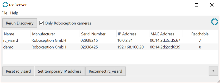
Fig. 11 Roboception’s discovery tool found two devices in the network.
The device named rc_visard is reachable from the host PC
(because in this example the host was in the same subnet 10.0.2.x).
The second device demo is not reachable as its IP address
is in a totally different network.
Note
You can re-run the discovery process anytime by clicking the
Rerun
Discovery
-button.
Note
The discovery tool is the central troubleshooting tool for checking whether Roboception 3D devices are properly connected and reachable by the host PC or not. For a detailed description, please refer to the discovery tool’s manual page.
If the rc_visard is reachable, a simple double-click on the respective row opens the sensor’s Web GUI which let’s you explore and visualize the data from the device. In this case, you can fully access the rc_visard already such that no further configuration of the network settings is required and you can skip the next section. You might still change the network settings according to your needs as described in Configure the rc_visard’s network settings or directly head over to Optimizations for high network loads.
Otherwise, as a first step to properly configure the rc_visard’s settings according to your network setup, you need to make it reachable from the host by assigning a temporary IP address as shown in the following.
Assign a temporary IP address
The discovery tool can be used to temporarily configure the rc_visard’s IP address and sub-network. This is particularly useful for making a misconfigured device temporarily reachable in the local network again.
- In the
rcdiscover-guiclick and select the row representing the non-reachable sensor. - Click the
Set temporary IP address-button. The respective dialog window pops up.- Make sure the correct sensor is selected.
- Change the IP and sub-net settings. As the goal is to temporarily put the sensor and the host into the same network, these temporary settings need to be chosen according to the host’s IP address and sub-net.
- Click the
Set temporary IP address-button and follow the dialog.
- Back in the main window, start a new discovery by clicking the
Rerun Discovery-button.
The rc_visard should now be discovered with the new, temporary IP address, and it should be reachable now.
Note
Since these settings are applied only temporarily, any reconnect – particularly any reboot – will set the rc_visard back to the former network settings.
Configure the rc_visard’s network settings
In general, two options exist to permanently configure the rc_visard’s network settings:
- the rc_visard’s Web GUI, and
- any configuration tool compatible with GigE Vision® 2.0.
We will give examples for both options below.
Note
As a preliminary for both options the sensor must be reachable. If it is not, please follow the instructions above to obtain temporary reachability by means of the discovery tool.
Option 1: The rc_visard’s Web GUI
The easiest way to access and permanently change the rc_visard’s network settings using a graphical user interface is its Web GUI.
The first step is to verify on the page of the Web GUI that the rc_visard is running the latest firmware (version 26.07).
The network settings can be found on the page. Here, you can easily check the currently applied IP configuration method and change the network settings according to your local network.
Note
While the Web GUI provides an intuitive graphical user interface to configure the network settings, in the back-end, it uses the rc_visard’s REST-API. This offers programmatic access to the full network configuration and can be used also by developers.
Option 2: Configuration via GenICam/GigE Vision®
The rc_visard complies to the GigE Vision® 2.0 standard, i.e. any configuration tool compatible with GigE Vision® can be used to configure the device and particularly its network settings. In the following we give two examples.
gc_config command-line tool
The command line GenICam tool gc_config gives full control
over the rc_visard’s network settings and lets you
configure any IP address, sub-net and gateway according to
your network setup.
It is part of Roboception’s open-source convenience layer rc_genicam_api,
which can be downloaded free of charge for Windows and Linux from https://github.com/roboception/rc_genicam_api/releases.
Example 1 - Static IP address
The following command configures an exemplary, static IP address of
192.168.188.10 and a sub-net mask of 255.255.0.0, where rc_visard_id is to
be replaced by the sensor’s serial number or user-defined name.
gc_config <rc_visard_id> -d 0 -p 1 -i 192.168.188.10 -s 255.255.0.0
Example 2 - DHCP (fall back to Link-Local)
If a DHCP server is available, gc_config lets you enable the
rc_visard’s auto-configuration option via:
gc_config <rc_visard_id> -d 1 -p 0
If no DHCP server is found by the device, it falls back to Link-Local.
Example 3 - Link-Local only
If you explicitly want to connect via Link-Local, gc_config lets
you disable both the static IP option and the DHCP option via:
gc_config <rc_visard_id> -d 0 -p 0
Reconnect the rc_visard and confirm proper network settings
In order to actually apply the changed network settings, the rc_visard needs to reconnect. Here several options exist:
Initiate a reconnect via the discovery tool:
- In the
rcdiscover-guiclick and select the respective sensor.- Click
Reconnect rc_visard. The reconnecting dialog window pops up.- Make sure the correct sensor is selected, click the
Reconnect-button and follow the dialog.Physically disconnect and connect the rc_visard from and to the network.
Any re-boot, e.g. by power cycling, will also cause the sensor to reconnect.
After reconnecting, you might check via the discovery tool that the desired settings are applied and that the rc_visard is reachable from your host.
The Baumer IpConfigTool
For changing the network configuration via GenICam using a graphical interface, we recommend using the IpConfigTool that is part of the Baumer GAPI SDK. The SDK can be downloaded free of charge for Windows and Linux from http://www.baumer.com.
After start-up, this tool scans for all available GigE Vision® sensors on the network. All rc_visard devices can be uniquely identified by their serial number and MAC address, which are both printed on the device.
- Select the rc_visard for which the network settings should be changed.
- In the Config options change the network settings according to your local network and press the Set button to commit the settings to the device.
- In order to actually apply the changed network settings, the rc_visard needs to reconnect which can be done
by means of the
rcdiscover-guior by simply physically disconnecting and connecting the rc_visard from and to the network.
Optimizations for high network loads
Note
It is strongly recommended to not skip this section
as most default settings will lead to improper network load.
A typical indicator for this is a received incomplete buffer
warning issued by the GenICam driver.
When working with the rc_visard, image data streaming causes high load in the network. In order to illustrate this, the following table shows the required bandwidth in percent, related to Gigabit Ethernet (i.e. 1 GBit/s).
| Image type | Image size | FPS | % of GigE Bandwidth |
|---|---|---|---|
| Left or right | 1280×960 pixel | 25 Hz | 24.6 % |
| Color information (U/V) | 1280×960 pixel | 25 Hz | 12.3 % |
| Disparity, Confidence and Error | 640×480 pixel (H) |
|
3.0 % |
| Disparity, Confidence and Error | 320×240 pixel (M) | 15 Hz | 3.7 % |
| Disparity, Confidence and Error | 214×160 pixel (L) | 25 Hz | 2.7 % |
For instance, streaming left color image at 25 Hz and Disparity at 3 Hz already requires more than 39.9 % network bandwidth of a 1 GBit/s Ethernet connection.
We therefore strongly recommend the following network optimizations if applicable.
Enabling “jumbo frames”
So called jumbo frames are UDP packets with more than the default 1500 bytes of payload. In network devices often this setting is referred to as maximum transmission unit (MTU).
Please adapt the MTU of all network devices the data packets are routed through. The maximally supported MTU by the rc_visard is 9000 bytes and is automatically negotiated on the device when connecting via GenICam. Hence, when directly connecting the rc_visard to the host, you only need to adapt the network interface card’s settings of that PC. However, if other network devices such as network switches are involved every individual device on the route needs to support jumbo frames and needs be configured properly. Please contact your network administrator to enable jumbo frames on them.
In the following we show examples how to set the host’s MTU to 9000 in Linux and Windows 10.
Temporarily
Enter the following command in the terminal.
ifconfig <interface> mtu 9000
Persistently
- Open the network manager
- Select interface and edit settings
- On “Ethernet” tab, change MTU to 9000
In Windows the settings for jumbo frames can be found in the advanced settings of the network driver:
- Open “Network Connections”
- Right-click on the network interface
- Choose “Properties”
- Click “Configure”
- On the “Advanced” tab, choose “Jumbo Packet”
- Select “9014 Bytes”
Increase the Receive Buffer Size (Linux only)
Another helpful option is to increase the network stack’s receive buffer size. Temporarily, this option can be set and tested via
sudo sysctl -w net.core.rmem_max=33554432
To make the changes persistent place a file 10-gev-perf.conf
with the line
net.core.rmem_max=33554432
into the directory /etc/sysctl.d.
Troubleshooting
The rc_visard is not discovered
Please make sure, the device is actually connected to the network.
For discovery across sub-nets under Linux reverse path filtering must be disabled. Using the debian package for Roboception’s discovery tool
rcdiscover-gui, this is or should have been done automatically during installation.
How to reset the rc_visard network settings to factory defaults?
The reset mechanism is only available for two minutes after a device startup. Hence, please reboot sensor if required, e.g. via power cycling.
- Open the
rcdiscover-gui, wait until the sensor is rebooted, which is indicated by a green LED, and start a discovery by pressing theRerun discoverybutton.- Click and select the row representing the respective device.
- Press the
Reset rc_visard-button. The resetting dialog window pops up.- Click the
Reset network-button and follow the dialog.- Back in the main window, click
Reconnect rc_visard. The reconnecting dialog window pops up.- Make sure the correct sensor is selected, click the
Reconnect-button and confirm.- Close the reconnecting dialog window.
- Start a new discovery by clicking the
Rerun Discovery-button.Note
A successful reset is indicated by a white status LED followed by a device reboot. If no reaction is noticeable, the two minute time slot may have passed, requiring another reboot.
Now, the rc_visard follows its default automatic network configuration routine and should either have an automatically assigned IP address from the DHCP server or a Link-Local address 169.254.x.x.
The rc_visard has a Link-Local address but is not reachable
If you want to connect the rc_visard via Link-Local and the discovery tool shows the sensor to have a proper Link-Local address 169.254.x.x assigned but still is not reachable, please check the network settings of your host. Most probably it is currently not configured for Link-Local connections.
A DHCP server is available but the rc_visard falls back to Link-Local
In some networks, the DHCP server is configured so that it only accepts known devices. In this case, the sensor’s MAC address (to be found on the device’s label) needs to be configured in the DHCP server. Please contact your network administrator.
I get many “incomplete buffer”-warnings
This indicates that data packets got lost in your network setup and could not be re-sent by the rc_visard fast enough. Please follow the instructions to optimize network settings for high loads.