Getting started with SilhouetteMatch
This tutorial shows how to set up the rc_visard to start using the SilhouetteMatch module and guides the reader to detecting the first objects.
Before we start
In order to go through this tutorial, the following prerequisites should be met:
The rc_visard is properly configured:
- The rc_visard is running the latest firmware (version 26.07) and the rc_visard’s license includes the SilhouetteMatch module. This can be verified on the page of the Web GUI.
One or more workpieces have been chosen and the templates for these objects have been generated:
- Suitable workpieces for SilhouetteMatch are described in the SilhouetteMatch user manual.
- The process for template generation is described in the Template generation tutorial. Alternatively, DXF files can directly be uploaded onto the rc_visard, for details see the same tutorial.
Setting up the scene
We recommend to mount the rc_visard on a tripod or a static support as explained in the rc_visard’s Mechanical interface description.
Note
The mounting should be stable such that the sensor remains static while SilhouetteMatch acquires data.
| Minimum distance | Maximum distance | |
|---|---|---|
| rc_visard 160 | 0.5 m | 1.5 m |
| rc_visard 65 | 0.2 m | 1.0 m |
For SilhouetteMatch to work, all objects must be placed directly on a common base plane. This plane must be as planar as possible and should have as little texture as possible. It should be colored such that there is some contrast between objects and the plane.
The rc_visard must be mounted somewhat parallel to the base plane—a tilt of up to 10 degrees is fine. Before SilhouetteMatch can detect objects, the base plane must be calibrated. In case of a static rc_visard and a static base plane, the calibration must be performed only once. If either the rc_visard or the base plane is moving (e.g. for picking objects from a load carrier with several separated layers of objects), the calibration must be performed whenever there might have been a change in position or orientation of the base plane relative to the rc_visard (e.g. when continuing to the next layer of objects in the bin). The scene must be set up such that the base plane can be detected reliably whenever a base-plane calibration is performed, as explained in Performing base-plane calibration.
For an rc_visard mounted on a robot, special handling is applied, as described in SilhouetteMatch Hand-eye calibration.
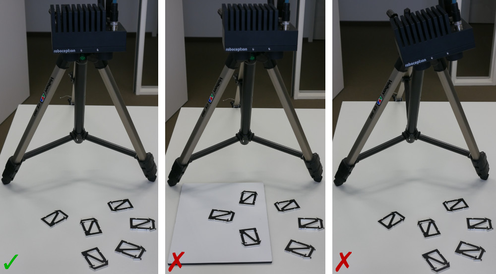
Fig. 35 Examples for good and bad base-plane configurations. Left: All objects are on the same plane. Middle: Objects are placed on different planes. Right: rc_visard is not approximately parallel to the base plane.
SilhouetteMatch is designed to work for unmixed scenes, meaning that only objects belonging to one specific template may be visible at a time. If multiple different objects are visible and their position is known approximately, regions of interest can be configured that enclose the objects belonging to each template. Moreover, it is assumed that all objects are right side up, so no objects are flipped.
Good illumination of the scene must be ensured; a gain of 0 db (see Improving image quality) on the Web GUI’s Camera page indicates that the scene is adequately illuminated. It is recommended to use diffuse illumination in order to avoid hard shadows.
Configuring image parameters
For base-plane calibration as well as for object detection, it’s most important that the images are well exposed. The tutorial about Tuning of camera images covers the steps required to get best quality images.
For stereo-based base-plane calibration (see Performing base-plane calibration), it’s additionally required to ensure high quality depth images, which is covered by the tutorial about Tuning of depth images. It is recommended to employ a rc_randomdot projector to allow dense reconstruction of a texture-less base plane.
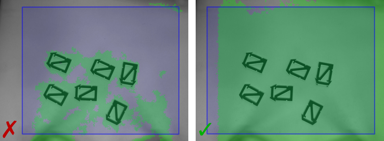
Fig. 36 Comparison of point cloud without (left) and with (right) projector. With projector, a much denser point cloud (green points) is produced, especially for the texture-less base plane.
SilhouetteMatch provides best results when the depth image quality is set to High. The projector should be operated in ExposureAlternateActive mode or the depth image Acquisition Mode should be set to Single + Out1, meaning that the projected pattern is not visible in the regular intensity images. Otherwise, the projector will interfere with SilhouetteMatch’s object detection process.
Configuring the load carrier
The configuration of the load carrier is described in detail in Configuring a load carrier.
Setting up SilhouetteMatch
After setting up the scene, SilhouetteMatch can now be configured.
Getting a template
Templates for new objects can be generated with Roboception’s template generation service.
The steps required for requesting a template are described in more detail in Template generation.
Uploading a template
The generated template must be uploaded to the rc_visard. The most convenient way to do this is via the Web GUI’s page. See the following video for a walk-through of the uploading process.
Video: Uploading a template

Configuring a region of interest
For both base-plane calibration and object detection, a 2D region of interest (ROI) can be applied. A ROI database is available on the system, in which ROIs can be stored and referred to during base-plane calibration or object detection by their name.
For configuring a new region of interest, the Web GUI offers an intuitive selection tool, which is shown in the following video.
Video: Configuring a ROI
Performing base-plane calibration
Base-plane calibration is an obligatory step before objects can be detected. During base-plane calibration, the plane on which the objects are placed (“base plane”) is estimated and—if successful—stored persistently on the rc_visard.
SilhouetteMatch provides two methods for estimating the base plane: AprilTag based and Stereo based. Both are introduced in the following.
AprilTag based
With AprilTag-based base-plane calibration, a plane is fitted through a set of AprilTags in the scene. At least three tags must be visible, placed such that they appear in the left and right camera image. The three tags should span a triangle around the objects, which is as large as possible.
Only tags of the family “36h11” are detected. The minimum size depends on the distance to the tags (see Tag reading for more information). AprilTags of family “36h11” can be downloaded from the apriltag-imgs repository. When cutting them out, please make sure to leave a white border around the AprilTags (see section AprilTag of the rc_visard manual).
The tags should be placed directly on the base plane. In case that is not possible, please refer to Offset parameter.
All “36h11” tags in the scene are used for calibration. A ROI can be used to select specific tags.
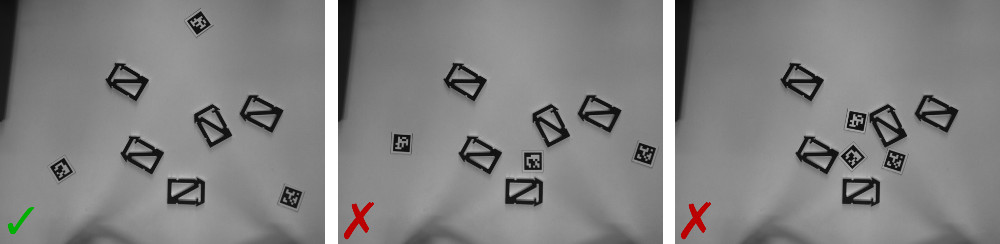
Fig. 37 Examples for good and bad AprilTag placements. Left: AprilTags span a large triangle, enclosing the objects. Middle: Triangle is degenerate. Right: Triangle is too small.
The following video shows how to perform AprilTag-based base-plane calibration via the Web GUI.
Video: AprilTag-based base-plane calibration

Stereo based
With Stereo-based base-plane calibration, the point cloud provided by the stereo matching
module is used.
SilhouetteMatch searches for planes in the point cloud and selects either the closest or farthest plane
from the rc_visard, depending on the plane_preference parameter.
For stereo-based base-plane calibration, a dense point cloud is important. Configuring image parameters explains how to ensure that.
For more control on which plane is selected, a ROI should be used (see Fig. 38).
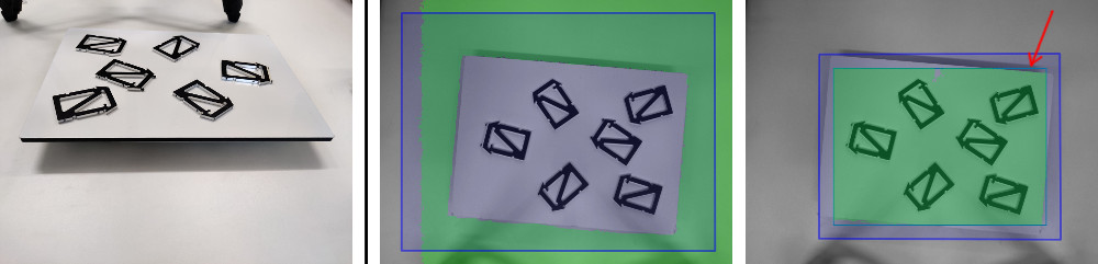
Fig. 38 Left: Scene with two planes in view of the rc_visard. Middle: By default, the most distant plane is selected. Right: By setting a ROI (petrol rectangle, marked with an arrow), the actual base-plane can be selected.
The following video shows how to perform stereo-based base-plane calibration via the Web GUI.
Video: Stereo-based base-plane calibration
Offset parameter
The base-plane calibration features an offset parameter that allows to shift the estimated
plane by some distance along the normal of the base plane.
This enables base-plane calibration even for scenes where it is not possible to calibrate
the base plane directly, but instead to calibrate a plane parallel to the actual base plane.
For example, the AprilTags might be printed on an aluminum pad with a thickness of 2 mm.
Therefore, when using these AprilTags for base-plane calibration, the estimated plane
is 2 mm above the actual base-plane.
By setting the offset parameter to -0.002, the estimated plane is shifted onto the
actual plane.
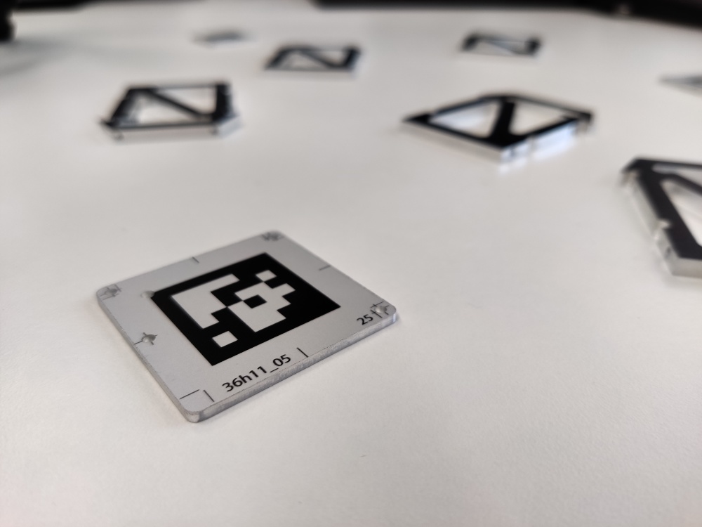
Fig. 39 Aluminum AprilTag pad with 2 mm thickness.
Detecting objects
After base-plane calibration is finished, objects can be detected.
Object detection can be triggered in the Try Out section of the Web GUI’s page. Triggering via REST-API is possible as well, as described in SilhouetteMatch Services.
In the Try Out section, the template that is to be detected must be selected by its name. Then, the detection is triggered with the Detect Objects button. The result will be shown in the table at the bottom of the page, as well as in the visualization images on top.
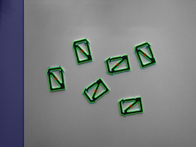
Fig. 40 Successful detection of a set of objects. Green: Detected objects. Light blue: Detected edges. Red dots: Returned (3D) poses of the object. Blue area on the left: Area where the left and right images do not overlap.
An object must be visible in the left and right image to be detected. As shown in Fig. 40, the area where the left and right image do not overlap is marked in blue.
By selecting a ROI, the search for objects can be limited to a part of the image.
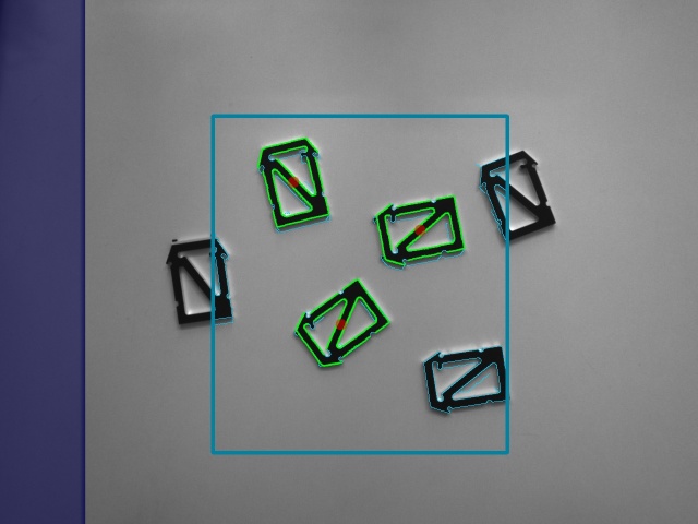
Fig. 41 A ROI (petrol rectangle) is applied to limit the search for objects.
The following video shows how to trigger the object detection via the Web GUI.
Video: Triggering object detection
The object detection process is influenced by a couple of parameters. The parameters can be adapted via the Web GUI as well as the REST-API. In the following, the parameters are described.
Quality
The Quality parameter controls the resolution of the images used for object detection. The lower, the faster is the computation, but details of the objects might get lost.
In case the rc_viscore is used with SilhouetteMatch, reducing the resolution to Medium or Low often gives better results, because object boundaries become sharper. Only when very small parts need to be detected, the full resolution of the rc_viscore should be used by setting the Quality to High.
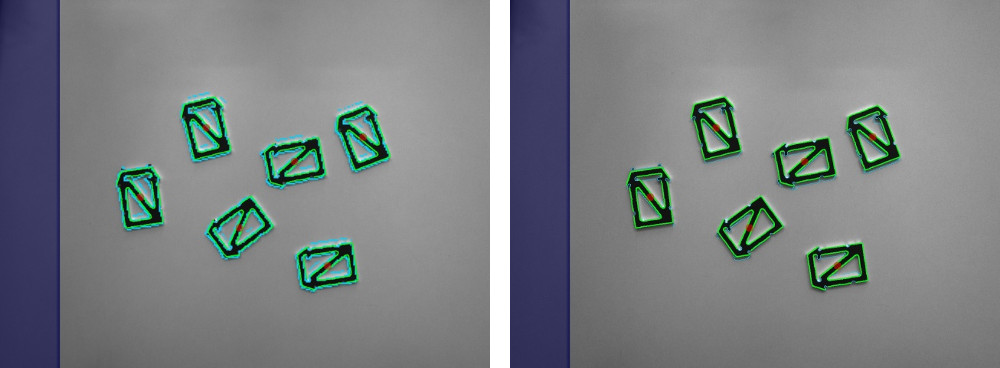
Fig. 42 Comparison of low (left) and high (right) quality.
Maximum Object Number
With the Maximum Object Number parameter the number of returned objects can be limited.
Maximum Matching Distance (pixel)
The Maximum Matching Distance (pixel) controls how exact the object template must match the detected edges in the image. The higher, the less strict the matching is, but the slower the computation will be. Too high values may also lead to false positive detections.
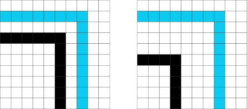
Fig. 43 Visualization of the Maximum Matching Distance parameter. Left: A value of 2 or greater would lead to a match between the template (black) and the detected edges (light blue). Right: A value of 4 or greater would lead to a match.
Matching Percentile
The Matching Percentile parameter controls what portion of the template must match to edges in the image. For example, a value of 0.9 means that 90% of the template edges must be closer than the Maximum Matching Distance to the edges in the image.
The lower, the less strict the matching is, but the slower the computation will be. Too low values may also lead to false positive detections.
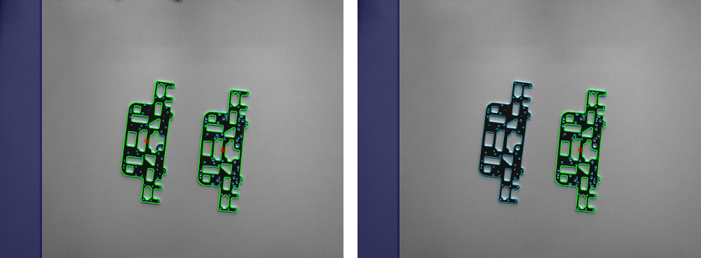
Fig. 44 Comparison of different Matching Percentile values. Left: With a value of 0.95, the flipped object is matched as well. Right: With a value of 0.98, the flipped object is not matched anymore.
Edge Sensitivity
The Edge Sensitivity parameter controls how many edges are detected in the image. The lower the value, the fewer edges are detected. It should be tuned such that all relevant edges are detected, without detecting noise edges.
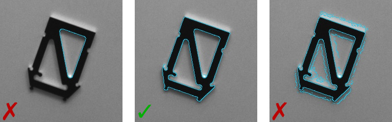
Fig. 45 Comparison of different Edge Sensitivity values. Left: With a value of 0.2, only few edges are detected. Middle: With a value of 0.7, all relevant edges are detected. Right: With a value of 0.95, many irrelevant noise edges are detected as well.