How to measure application accuracy
This tutorial shows how to measure application accuracy with KUKA robots, e.g. for grasping objects. The accuracy depends on the absolute accuracy of the robot (i.e. not repeatability) and the accuracy of the hand-eye calibration. Especially errors in the orientation of the sensor may have serious effects.
Note
The hand-eye calibration has to be performed every time the sensor is moved relative to the robot base.
Before we start
To verify the hand-eye calibration you need a robot with a pointing tool tip, a Roboception 3D camera, and a printer to print out the Robot-Test-Grid. We assume that the robot cell is operational, the TCP of the pointing tool tip is set and a hand-eye calibration has already been performed.
The hand-eye calibration procedure is described in detail in the rc_visard’s hand-eye calibration documentation. See Hand-Eye Calibration for a Universal Robots tutorial.
The KUKA KRL sample program can be downloaded here: https://github.com/roboception/eki_examples/tree/master/examples/MeasureApplicationAccuracy. The program includes the KUKA KRL src and dat file and a printable version of the ‘Robot-Test-Grid’.
Program overview
The robot will trigger an AprilTag detection and move to the target on the robot test grid. In an ideal world the position of the tool tip should be exactly in the middle of the target and the orientation should be perpendicular to the AprilTags.
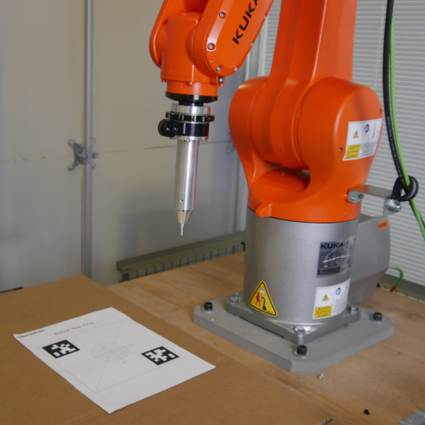
Fig. 67 Overview of the test setup
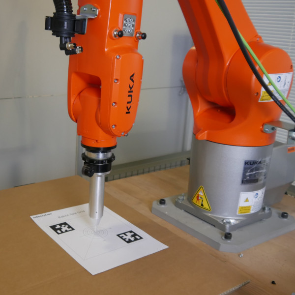
Fig. 68 Robot pointing on target
It can also help to perform several measurements in the relevant working areas (e.g. pick area, place area etc.) of your robot cell. This might help in troubleshooting to see if the deviation is the same or if it changes depending on the position of the robot test grid.
Measure application accuracy
Warning
Do not drive the robot in automatic mode or with high speed! Always reduce the speed of the robot and use the manual mode.
Warning
No collision checks are active. Please make sure the robot has a collision-free path to the target position.
- Print the robot test grid and stick it to a plane surface (e.g. cardboard).
- Place the robot test grid in the robot cell and make sure it is completely visible by the sensor.
- Run the sample program, which will move the TCP of the robot to the robot test grid target in PTP motion.
- The program will stop as soon the target position is reached.
- Measure the deviation of the tool tip on the target with a ruler or a caliper gauge.
Note
Pro tip: To measure the translational deviation, the tool can be pushed into the cardboard by manually moving the robot in tool frame. To do this, move the tool in the direction of the Z axis until the tip of the tool pierces the cardboard. Then, move the robot back again and remove the robot test grid from the cell. Now you can easily measure the deviation using a caliper gauge.
Troubleshooting
If the tool tip is not positioned accurately, this can have several causes, ranging from poor hand-eye calibration to an incorrectly set robot. The following points show possible causes and give hints how to solve them.
Inaccurate TCP configuration
Inaccurate poses during hand-eye calibration
Insufficient poses during hand-eye calibration
Wiggling robot or calibration grid during hand-eye calibration
Inaccurate robot
If you have any questions or issues, please do not hesitate to contact Roboception support with a detailed error description.