FAQs and troubleshooting
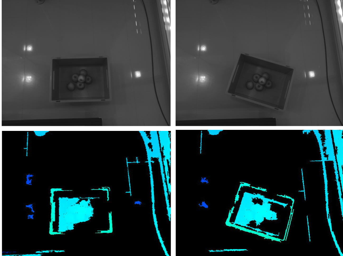
The load carrier rim is not visible in the depth image
One common case for missing the rim in depth images takes place when one of the edges of the load carrier is parallel to the baseline of the stereo system. It can be easily determined if this the case by slightly rotating the load carrier and observing if the orientation has an effect on the appearance of the object in the depth image. When this happens, the rc_randomdot projector can be added to the rc_visard to increase the depth image density.
The load carrier is not detected or not detected robustly
Is the load carrier fully visible in both the left and right camera image?
Does the load carrier rim appear in the depth image? (cfr. Detecting the load carrier)
Is the load carrier inside the region of interest (if specified)?
Are the dimensions of the load carrier model correct? (cfr. Add a new load carrier)
The manufacturer’s dimensions might not be completely accurate. If the load carrier is not detected, we recommended to double check the configured dimensions. Additionally, one can try increasing the
model_toleranceparameter (e.g. to the maximum value).Make sure the
min_plausibilityparameter is not set too high.
The load carrier is not placed on a horizontal surface
By default, the LoadCarrier module assumes that the load carrier is located on a horizontal
surface. If that’s not the case, one needs set the assume_gravity_aligned parameter to false.
Alternatively, one can provide the load carrier orientation as a prior with the load carrier model. The orientation prior can be set in the Web GUI’s page and via the REST-API, which is described in the following.
Two sample cases are shown in Fig. 17 for the external pose frame (left) and the camera pose frame (right).
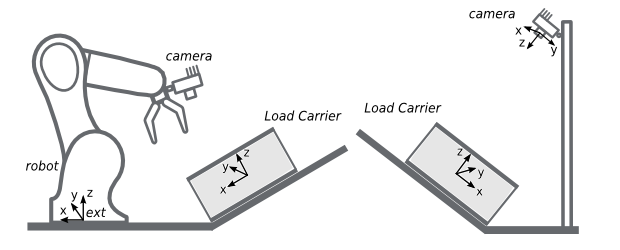
Fig. 17 Load carrier not placed on a horizontal surface
In the left case of Fig. 17, the load carrier (tilted-load-carrier-ext)
is rotated by an angle \(\theta\) around the \(y\)
axis of the external coordinate system. The load carrier orientation is given by the
following quaternion: \(\left[0, \sin(\theta/2), 0, \cos(\theta/2)\right]\).
Request to the REST-API for configuring tilted-load-carrier-ext
Here we make the assumption that
tilted-load-carrier-exthas the same dimensions ofmy-load-carrier-1(cfr. Load carriers with a solid rim) and that the angle \(\theta\) is 30 deg.To trigger the
set_load_carrierservice via the REST-API fortilted-load-carrier-ext, one needs to send a PUT request to the URLhttp://<rc-visard-ip>/api/v2/nodes/rc_load_carrier_db/services/set_load_carrier, where<rc-visard-ip>should be replaced by the actual IP of the rc_visard.The PUT body should include the following data, in JSON:
{
  "args": {
    "load_carrier": {
      "id": "tilted-load-carrier-ext",
      "outer_dimensions": {
        "x": 0.4,
        "y": 0.3,
        "z": 0.22
      },
      "inner_dimensions": {
        "x": 0.37,
        "y": 0.27,
        "z": 0.215
      },
      "pose_frame": "external",
      "pose": {
        "orientation": {
          "x": 0,
          "y": 0.25882,
          "z": 0,
          "w": 0.96593
        }
      },
      "pose_type": "ORIENTATION_PRIOR"
    }
  }
}
In the right case of Fig. 17, the load carrier
(tilted-load-carrier-cam) is parallel to the image plane.
Its orientation in the camera coordinate system is
\(\left[\sqrt(2)/2, -\sqrt(2)/2, 0, 0\right]\).
Request to the REST-API for configuring tilted-load-carrier-cam
Here we make the assumption that
tilted-load-carrier-camhas the same dimensions ofmy-load-carrier-1(cfr. Load carriers with a solid rim).To trigger the
set_load_carrierservice via the REST-API fortilted-load-carrier-ext, one needs to send a PUT request to the URLhttp://<rc-visard-ip>/api/v2/nodes/rc_load_carrier_db/services/set_load_carrier, where<rc-visard-ip>should be replaced by the actual IP of the rc_visard.The PUT body should include the following data, in JSON:
{
  "args": {
    "load_carrier": {
      "id": "tilted-load-carrier-cam",
      "outer_dimensions": {
        "x": 0.4,
        "y": 0.3,
        "z": 0.22
      },
      "inner_dimensions": {
        "x": 0.37,
        "y": 0.27,
        "z": 0.215
      },
      "pose_frame": "camera",
      "pose": {
        "orientation": {
          "x": 0.70711,
          "y": -0.70711,
          "z": 0,
          "w": 0
        }
      },
      "pose_type": "ORIENTATION_PRIOR"
    }
  }
}
The value of the assume_gravity_aligned parameter will be ignored for load carriers with an orientation prior set.
The load carrier is deformed
One can try increasing the model_tolerance parameter (e.g.
to the maximum value).
For significantly deformed load carriers, the detection algorithm might not provide reliable results. This can for example be the case of cardboard boxes after several uses. An alternative for such cases is to fix the load carrier placement and specify the exact pose of the load carrier (please see Setting the exact pose or an orientation prior of a load carrier for further discussion).
The load carrier floor is detected as load carrier content
This means that either the load carrier \(z\) inner dimension is too large or the reconstruction of the load carrier floor is noisy.
To improve the detection result as shown in Fig. 18, two options are available:
- Decrease the load carrier \(z\) inner dimension
- Increase the
crop_distanceparameter (recommended for noisy data)
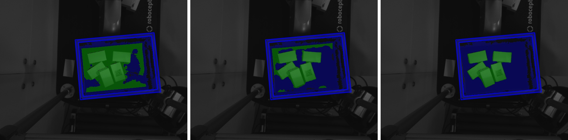
Fig. 18 Removing detection of the bin floor
Objects on the load carrier floor are not detected as load carrier content
crop_distance parameter is too large.There are multiple load carriers of the same type in the scene
detect_load_carrier or detect_filling_level request.
However, when a load carrier is used with the rc_reason modules, only a
single load carrier will be detected. If there are multiple load carriers of
the same type in the scene, we recommended to specify
one ore more regions of interest, each one including one load carrier instance.My load carrier doesn’t move. How do I speed up my application?