Setting up the gripper
This tutorial shows how to set up a gripper for the CollisionCheck module.
The gripper in the CollisionCheck module represents the collision geometry of the real gripper mounted to the robot. That means, the outer geometry of the gripper has to be modeled in a way that it completely contains all parts of the robot’s gripper, including cables, connectors etc.
Before we start
In order to go through this tutorial, the following prerequisites should be met:
The rc_visard is properly configured:
- The rc_visard is running the latest firmware (version 26.04) and the rc_visard’s license includes the CollisionCheck module. This can be verified on the page of the Web GUI.
Add a new gripper
In this tutorial we will show how to model the sample gripper shown in Fig. 47.
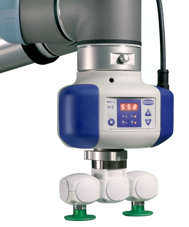
Fig. 47 Sample vacuum gripper to model for collision checking
The easiest way to create a gripper is via the Web GUI’s or page. The Grippers section lists all defined grippers and allows to edit and remove them. All configured grippers are globally available to all detection modules that can use CollisionCheck. To create a new gripper, click on “+ Add a new gripper”.
A dialog window opens that allows creating the gripper. A 3D visualization on the left helps to check the created gripper geometry. Initially, it only shows the robot flange with a default radius and the flange coordinate frame.
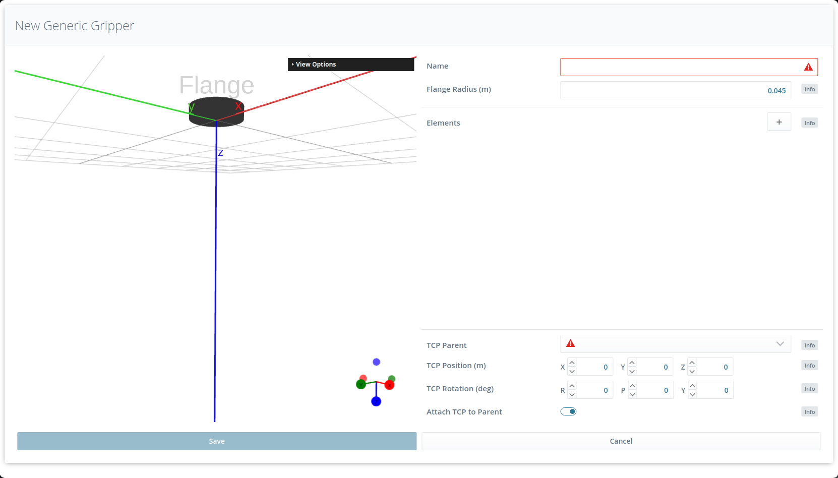
Fig. 48 Creator dialog for gripper creation
The gripper should be modeled in a way such that each element is completely contained in a cylinder or box.
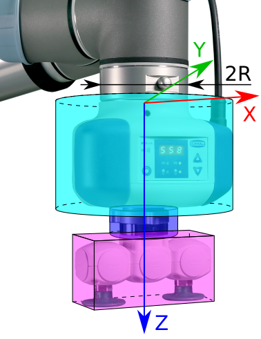
Fig. 49 Modeling of the gripper geometry with cylinders and boxes. R is the outer flange radius. The axes correspond to the flange coordinate frame.
Flange radius
The flange radius is the outer radius of the robot’s flange (see Fig. 49).
It is used during a safety check if the check_flange parameter is enabled (see Check Flange).
It is required to set the flange radius even if the check_flange functionality will not be used.
Gripper elements
The gripper is built in the direction from the flange to the Tool Center Point (TCP) and consists of a list of elements which can be cylinders and boxes. To add a new element, click on the + symbol in the Elements section (see Fig. 48).
The first element of our sample gripper is a vacuum generator. We model it as a cylinder with the same height as the vacuum generator (0.083 m) and a radius corresponding to the maximal elongation of the vacuum generator along the z axis of the flange coordinate frame. It is important that the modeled collision geometry completely includes the real gripper element to prevent undetected collisions. Since the vacuum generator is mounted directly on the flange, we choose ‘Flange’ as parent element, which is selected by default for the first element. The position of the cylinder in the flange coordinate frame is computed automatically when the button to automatically attach the element to its parent is active (see Fig. 50). The position coordinates will in this case be 0 in x and y coordinates and half of the element’s height in z direction. The origin of each element is located in its geometric center and the pose of each element is defined in the origin of its parent element. The origin of the flange element is located in the center of the flange’s bottom plane.
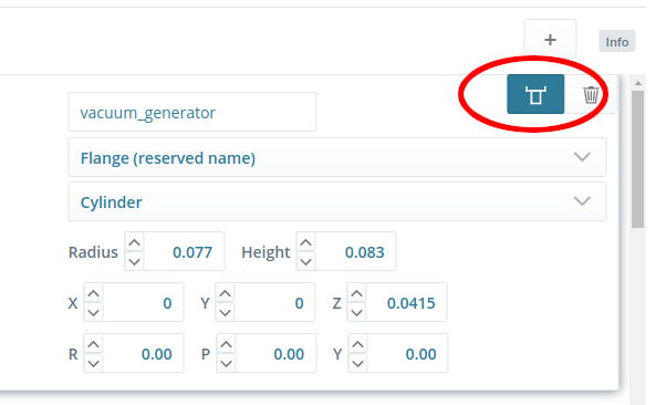
Fig. 50 The option for automatically attaching the element to its parent element is active.
The second element of the gripper is a cylindrical connector part which we will also model as a cylinder. We use the height of the connector as height of the cylinder for the collision geometry. The radius of the cylinder again is the maximal elongation along the flange z axis. The parent of this cylinder is the vacuum generator and we again use the automatic attachment (on by default) to position the cylinder exactly below its parent element. In this case, the z coordinate of the connector is half of the sum of the parent’s and connector’s heights, because the origin of each element is located in its geometric center and the pose of each element is defined in the origin of its parent element (see also Fig. 51).

Fig. 51 Computation of an element’s position in the parent element’s origin
The last element of the gripper is the suction part. It will be modeled as a box because it is elongated in one direction. We choose the box dimensions such that the suction part is completely contained in the box. It is important to check that the orientation of the modeled box corresponds to the orientation of the real gripper element. In this case, the longer side of the box is in the x-direction of the flange coordinate frame. The parent element of the suction part is the connector and its position is again computed automatically using the attaching option to mount this part directly in the center below the connector.
TCP position
Finally, we have to set the TCP position. First, we have to choose the parent element for defining the TCP pose, which in our case is the suction part. By default, the TCP is automatically attached to the center of the bottom plane of the parent element. The position of the TCP is used to decide whether a grasp is collision-free or not: Whenever any part of the gripper would be in collision with the load carrier while the TCP is at the grasp point, the grasp will be detected as collision. Since suction grippers have to slightly push against an object to grasp it, the TCP must be set to a position inside the suction part, e.g. 2 mm. Thus, we decrease the TCP position that results from the automatic attachment by 2mm in z direction, i.e. from (0, 0, 0.02) to (0, 0, 0.018), so that the TCP is shifted along the z-axis by 2 mm in negative direction.
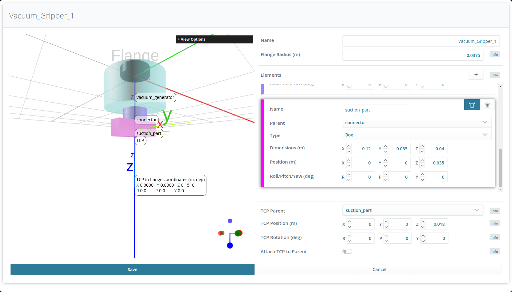
Fig. 52 Final model of the gripper geometry
Checking and saving the gripper
In the 3D gripper visualization, the position and orientation of the TCP in the flange coordinate frame is displayed.
Warning
The computed pose of the TCP in the flange coordinate frame must be the same as the TCP pose defined in the robot controller to ensure that the gripper geometry is modeled correctly with respect to the gripper height.
The last step of the gripper creation is to save the gripper. It will now be shown in the Grippers section of the Web GUI’s and page and can be used in all rc_reason modules.