End-to-End System Accuracy Test
Introduction
Vision-guided robot systems can show positioning inaccuracies that often stem from a degraded hand-eye calibration, typically caused by small physical changes like camera movements. These inaccuracies manifest as inconsistent positioning - objects may be gripped with an offset that varies depending on their workspace position. While this offset can be temporarily compensated for in a specific orientation, the problem will reappear when objects are moved to different locations.
This tutorial guides you through a systematic verification process to assess your complete system’s accuracy with KUKA robots and determine if recalibration is necessary. The test uses AprilTag markers and a precision pointing tool to verify the accuracy of the entire chain from vision detection to physical robot positioning.
Required materials and prerequisites
Before starting the verification:
- Ensure your robot cell is operational
- Confirm that a hand-eye calibration has been performed
For details on the hand-eye calibration procedure, refer to the Hand-eye calibration documentation.
For this verification process, you will need:
- A KUKA robot with a precision pointing tool (such as a dart tip)
- A Roboception 3D camera
- The verification sheet (printed in high quality)
- A soft mounting surface (foam board or cardboard)
Verification sheet
Print the verification sheet in high quality, black and white. It is available in:
A4 formatLetter format
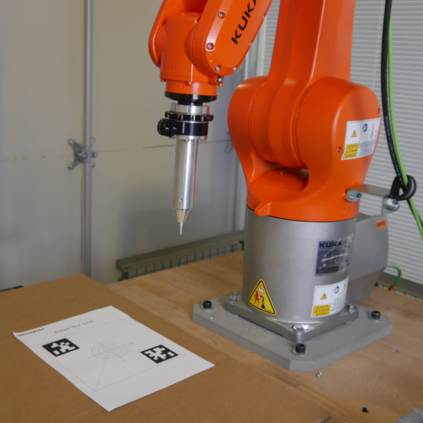
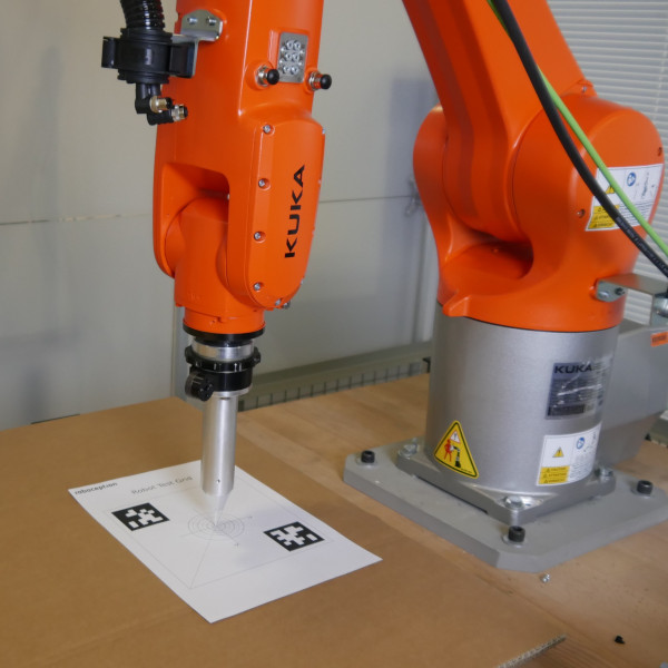
The sheet displays two AprilTags positioned in opposite corners with a center crosshair marker between them. Mount the printed sheet on an planar but soft surface, such as foam board or cardboard. This allows the pointing tip to safely penetrate the paper if positioning offsets occur during verification.
Tool requirements and configuration
Required tool components
A precision pointing tool is required for this verification process. This can be either a dedicated pointing tool (such as a dart tip) mounted directly to the robot flange, or a pointing tip attached to a flat surface that can be picked up using a suction gripper. The key requirement is that the tool provides a precise, sharp point for accurate measurements.
TCP configuration
Configure the tool settings according to your KUKA robot system manual:
- Define a new tool
- Set the TCP to match the physical tip position
- Configure the tool’s mass and center of gravity
- Save the tool configuration
Before proceeding, verify your TCP configuration:
- Position the tool tip near a fixed reference point
- Use the manual mode to rotate the tool around its Z-axis
- The physical tip should remain perfectly stationary during rotation
- If the tip moves in a circular pattern, reconfigure the TCP
Warning
TCP accuracy is crucial for reliable measurements. Even small offsets can significantly impact your verification results.
Measure application accuracy
- Download the KUKA KRL sample program from: https://github.com/roboception/eki_examples/tree/master/examples/MeasureApplicationAccuracy
- Print the robot test grid and stick it to a plane surface (e.g. cardboard).
- Place the robot test grid in the robot cell and make sure it is completely visible by the camera.
- Run the sample program, which will move the TCP of the robot to the robot test grid target in PTP motion.
- The program will stop as soon the target position is reached.
- Measure the deviation of the tool tip on the target with a ruler or a caliper gauge.
Warning
Do not drive the robot in automatic mode or with high speed! Always reduce the speed of the robot and use the manual mode.
Warning
No collision checks are active. Please make sure the robot has a collision-free path to the target position.
It can also help to perform several measurements in the relevant working areas (e.g. pick area, place area etc.) of your robot cell. This might help in troubleshooting to see if the deviation is the same or if it changes depending on the position of the robot test grid.
Note
To measure the translational deviation, the tool can be pushed into the cardboard by manually moving the robot in tool frame. To do this, move the tool in the direction of the Z axis until the tip of the tool pierces the paper. After removing the robot test grid from the cell, you can easily measure the deviation using a caliper gauge.
Interpreting results and next steps
A well-calibrated system will show consistent alignment between the tool tip and center marker across all test positions.
If the tool tip consistently deviates from the center marker, consider these potential causes:
Inaccurate TCP configuration
The most common cause of verification failures is an imprecise TCP configuration. Verify your TCP setup using the rotation test described in the TCP configuration section.
Inaccurate robot
While industrial robots typically offer excellent repeatability (sub-millimeter range), their absolute accuracy may vary. This affects positions provided by the vision system. Some robot manufacturers offer world calibration services to improve absolute accuracy.
Robot accuracy vs. repeatability
Industrial robots excel at repeatability (consistently returning to the same position), typically achieving sub-millimeter precision. However, absolute accuracy (moving to exact world coordinates) can be less precise. When a vision system provides target coordinates, this absolute accuracy becomes crucial.
The difference between the robot’s internal coordinate system and real-world coordinates can lead to systematic offsets in your verification measurements. Some robot manufacturers offer world calibration services to minimize these discrepancies between the robot’s coordinate system and real-world coordinates.
Note
If you observe position-dependent deviations during verification (different offsets at different locations), this might indicate a world calibration issue rather than a hand-eye calibration problem.
If you have any questions or issues, please do not hesitate to contact Roboception support with a detailed error description.


